5g core network architecture 3gpp | 5g core network elements | 5g architecture | 5g interface architecture | 5g standalone architecture(SA) | 5G non-standalone architecture(NSA) | 5g core network architecture diagram | 5g Core Network Functions | 4gG EPC vs. 5GC | CUPS Architecture | 5g Service Based Architecture 3GPP
5g core network architecture
5g core network architecture
3GPP is a standard body that is defining both a new 5G core network (5GC) and a new radio access technology called 5G “New Radio” (NR). There are several options available to integrate between different generations of access network technology with the core network. There are mainly two deployment models defined by 3GPP which are independent (SA) and non-independent (NSA) deployment models. In the SA model, only one radio access technology, either 5G NR or LTE radio cells, and the core networks operate alone. In the NSA model, both NR radio cells and LTE radio cells use dual connectivity to provide radio access and the core network using EPC or 5GC.
5G Core Network SA and NSA Architecture
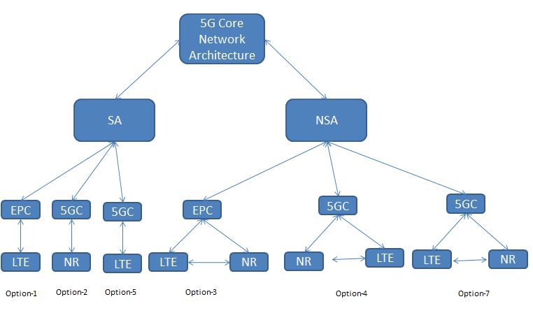
There are several 5G core network deployment options defined by 3GPP.
1. Standalone architecture (SA).
Independent radio access works independently in the SA architecture. It is like a separate network where both access networks provide user plan functionality and control. The handover will take place between the 4G and 5G network.
2. Non-standalone architecture (NSA).
Multiple radio access networks in NSA network architecture. In non-standalone architecture (NSA), 5G NR radio cells are paired with 4G LTE radio cells using dual connectivity to provide radio access and the core network can be EPC or 5GC.
UE will use radio resources from two different access networks NR (gNG) and LTE (eNB) both.
In SA architecture we have 3 implementation options.
1. Option 1: EPC and LTE eNB access. This is the current 4G architecture.
2. Option 2: access to 5GC and NR gNB and
3. Option 5: 5GC and LTE ng-eNB access
In the NSA architecture we have 3 implementation options.
1. Option 3: EPC and an LTE eNB acting as master and en-gNB NR acting as secondary.
2. Option 4: 5GC and one NR gNB acting as master and LTE ng-eNB acting as secondary.
3. Option 7: 5GC and one LTE ng-eNB acting as master and one NR gNB acting as secondary.
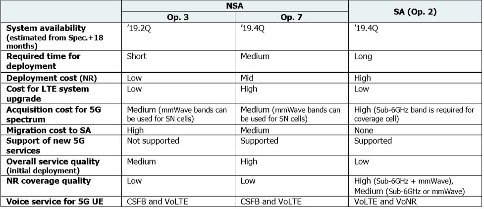
5g SA vs. NSA architecture comparison

TCO analysis for 5G SA vs. NSA deployment
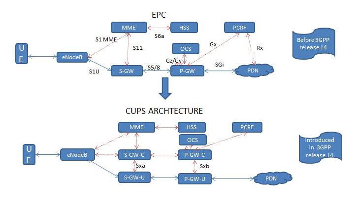
4G EPC Recap:
The LTE EPC consists of many network elements mentioned below.
MME (Mobility management Entity):
- It is used to manage the mobility, security and session of UE.
- It works on control plan.
- Tracking and paging of UE in idle mode.
- Termination point for NAS.
S-GW (Serving Gateway):
- Works on user plan.
- Transport user data traffic between UE and other network.
- Responsible for interconnect between RAN and EPC.
- Anchor point for intra-LTE mobility
- It logically connected to PDN-GW.
P-GW (PDN Gateway):
- Works on user plan.
- Interconnect between the EPC and other network for example IMS or internet.
- IP allocation, policy control and charging.
HSS (Home Subscriber Server):
- This is the database for storing user profile.
- It also play role in mobility management, call and session setup, user authentication and access authorization.
PCRF (Policy and Charging Rules Function):
- Provide qos (quality of service) information to p-gw.
- It also provides charging rule and any specific services for a user.
Moving towards 5G Core
We have seen EPC nodes and it’s functionalities for 4G network. Now the same functionalities will be there in 5G core. In 5G core some nodes are decomposed and divided into many individual nodes. On the other hand some nodes are combined into a single node. In 5G, automation is one of the key requirements. To fulfil the automation requirement control plan and user plan separation is must. We can achieve this control plan and user plan separation by implementing NFVI (Network Function Virtualization) and SDN. 5G core network architecture meets these requirements. 5G core is also talking about implementation of cloud native application.
5G Service based Architecture
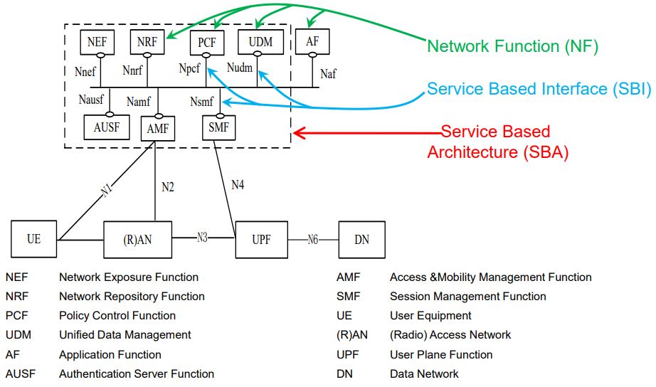
AMF (Access and Mobility Management Function):
- It provides similar functionality like MME in 4G network.
- It is responsible for NAS connection maintenance.
- UE registration procedure.
- Paging
- Authentication of subscriber in registration and de-registration process.
SMF (Session Management Function):
- It provides session management functionality of MME in 4G network.
- It also provides some control plan functionality of S-GW and P-GW.
- IP address allocation to UE.
AUSF (Authentication Server Function):
- It is responsible for obtaining authentication vectors from UDM.
UPF (User Plane Function):
- This is responsible for carrying user traffic similar to S-GW and P-GW functionality in 4G network.
- It is anchoring UE IP.
- Provides QoS enforcement functionality.
PCF (Policy Control Function):
- It performs similar functionalities like PCRF.
- Provides policy rule, QoS etc.
NSSF (Network Slice Selection Function):
- This is the new capability introduced in 5GC.
- This allows us to slice the network based on the services.
- It is responsible for marinating network slice instance.
- UE shall be configured with list of network slice for accessing services.
N3IWF (Non-3GPP access Inter-Working Function):
- Perform same functionalities like ePDG in 4G EPC.
- It is responsible for AMF selection when UE is trying to register from non-trusted access network like WiFi.
- UE shall have active connection with AMF from 5G RAN as well as WiFi access network.
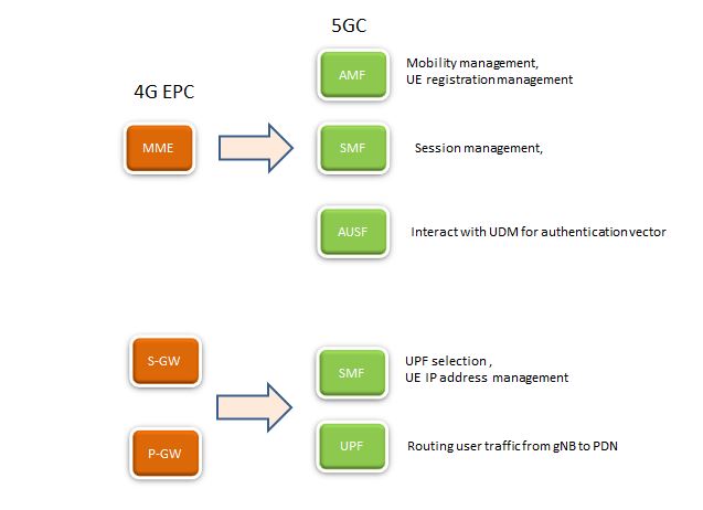
As shown in above diagram, 4G EPC MME functionality has been divided into AMF, the SMF, and the AUSF.
In 4G EPC, S-GW and P-GW functionalities have both been merged and divided into separate control plane and user plane functions in 5GC, SMF and UPF are the elements which perform the same functionalities.
Downlink traffic is buffered at UPF when is in idle mode. UPF inform SMF and SMF inform AMF for paging.
