RAN Architecture Evolution To 5g Network Architecture | 5g RAN Architecture | 5G RAN deployment architecture | Deployment Architecture And Placement Of RAN And Core Function For Various Services
5g ran architecture
Here we will discuss about RAN architecture evolution to 5g network. we are seeing major changes and improvements in RAN architecture evolution in 5g. There are various RAN architecture 5g deployment model evolved in 5g network architecture.
The 3GPP 5G RAN design, presented in release fifteen and named NG-RAN, features a new nomenclature, interfaces and practical modules. The NG-RAN consists of a group of radio base stations (known as gNB) connected to the 5G core network (5GC) and to all the different ones. The gNB incorporates 3 main practical modules: the Centralized Unit (CU), the Distributed Unit (DU), and also the Radio Unit (RU), which could be implemented in multiple mixes. The new main interface is that the F1 interface between DU and CU is expected to be followed in all OEM. Standardization of an additional lower layer interface between DU and RU is not yet finalized and many organizations are working on it. Centralized unit further broken down into the CU User Plane (CU-UP) and CU control Plane (CU-CP), each of which connects to the DU via the F1-U interface and F1-C interface. This new 5G RAN design is outlined in 3GPP TS 38-401.
5G RAN network deployment architecture option:
DRAN Option ,
CRAN Option
Which is the suitable RAN architecture in 5g network architecture?
The selection of the RAN implementation model is very crucial for the service provider, since there is no clear guideline. The implementation of RAN in the 5g network architecture will be based on the use case requirement and will be different from one region to another. For example, an ultra-low latency factory automation network would require DU / CU close to or integrated with the RU. The selection of the RAN architecture will also depend on the existing network, cost, operating model, etc…
5G RAN and Transport Network co-relation:
Below diagram represents transport network integration with RAN and core functional component.

In this diagram we can see there are basically three category of transport network placed between RAN and core functional component. Fronthaul transport network between RU and DU, midhaul transport network between DU and CU and backhaul transport network between CU and 5G core network. RAN technology only does not specify the architecture. If a service provider wanted to provide services like ultra-low-latency and ultra-reliable services then network design will be different. DU, CU shall be deployed together at cell site to meet this kind of critical latency and reliability requirements. So, we can conclude that 5G RAN deployment architecture is depend on RAN design, transport network and service requirements.
In 5G RAN and core function deployment will not be the uniform. It will be varied based on use case and service requirements. Macro cells and small cells connect to external networks through UPF in the 5G core through different stages aggregation transport network nodes. These aggregation transport network nodes decrease toward the core, therefore increase in transport capacity. For example, for a network with 1,000 Tier 1 sites, there might be 100 Tier 2 sites and 10 Tier 3 sites.
NGMN guidelines for one-way latency from the cell site to a Tier 1, Tier 2 and Tier 3 aggregation site are 0.6 ms, 1.2 ms and 4.2 ms respectively.
Deployment Architecture And Placement Of RAN And Core Function For Various Services:
- Deployment architecture for mobile broadband service where latency requirement is <10ms.
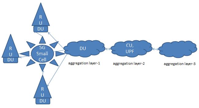
Here the CU and the UPF are placed at the aggregation layer 2 and DU’s are deployed in distributed manner at the aggregation layer 1 or to the cell site.
- Deployment architecture for services like automated guided vehicle where latency requirement is <5ms.
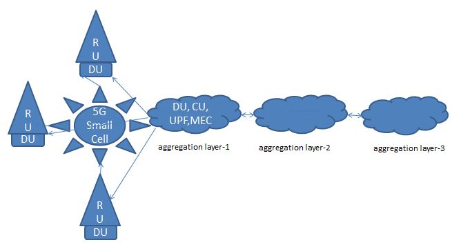
Here UPF is deployed in aggregation layer 1 to meet 5ms latency requirement. MEC application shall also be placed aggregation layer 1 to meet latency requirement that is required for MEC applications.
- Deployment architecture for services like industrial automation where latency requirement is <1ms.
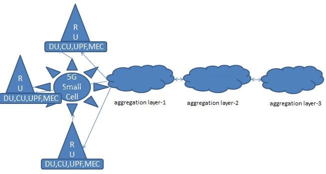
Here CU, DU, UPF, MEC are deployed along with RU to meet ultra-low latency requirements.